Background
This case introduces the application of Acrel DJSF1352-RN DC energy meter in the DC side of a photovoltaic system in Saudi Arabia. It is mainly used to measure the DC current in the photovoltaic system, and cooperate with current shunts to measure, communicate and control the circuit system.
Project Overview
The company is located in Saudi Arabia. The company is mainly engaged in the installation, construction and maintenance of small photovoltaic power generation center projects in Bulgaria and surrounding countries. The customer wants to use DC meters and hall sensors or current shunts for monitoring, metering and communication of current and voltage at the DC side of the photovoltaic system, and demands that the DC energy meter would be able to measure two channels of DC circuits.
DJSF1352-RN/D DC Energy Meters
DJSF1352-RN rail-mounted DC power meter with double DC input channels, designed for telecommunications base stations, DC charging piles, solar photovoltaic and other applications, this series of meters can measure the voltage, current, power and forward and reverse energy and so on in the DC system. In the actual use of the site, you can measure the total power, but also measure the energy within a specified period of time. The test results can be used for local display, but also with industrial control equipment, computers to form a measurement and control system.
The meter can have an infrared communication interface and RS-485 communication interface and supports Modbus-RTU protocol and DLT645-97 (07) protocol at the same time. The meter can have relay alarm output and digital input function; You can set the ratio, alarm, and communication through the meter panel keys according to different requirements. The meter can have event recording of the switch (Modbus protocol), programming and event setting records (645 protocol), instantaneous and timing freeze function of data (645 protocol), maximum and minimum value recording function of voltage and current power.
Type and Function Description

Note: when dual DC input(D)function is selected, if Hall current sensor input is used in
current channel, a power supply module shall be provided to supply power to the second Hall sensor; if D function is not provided, the built-in power supply of electric meter can be used.
| Technical parameters | Index | ||
| Input | Nominal value | Voltage input range | Current input |
| DC 0-1000V | Hall sensor:0-20mA、4-20mA、0-5V,0-10V and so on | ||
| DC 0-1000V | |||
| See the physical wiring diagram | |||
| Overload | 1.2 times rated (continuous); 2 times rated/1 second; | ||
| Power consumption | Voltage: ≤0.2VA, current ≤0.1VA | ||
| Accuracy class | Class 1 | ||
| Function | Display | 8-bit segment LCD screen (LCD) | |
| Communication Interface | RS485(two options) | ||
| Communication protocol | Modbus-RTU, DL/T 645-2007 | ||
| Switch | Switch output | 2 Relay outputs, 2A/30VDC or 2A/250VAC | |
| Switch input | 2 dry contact inputs | ||
| Pulse output | A second pulse output, an energy pulse output | ||
| See the SYS->PLUS display in the meter menu settings. For example, The meter displays 100, which is 100imp/kWh | |||
| Power Supply | Voltage range | AC/DC 85-265V or DC24V(±10%) or DC48V(±10%) | |
| Power consumption | ≤ 3W | ||
| Power frequency withstand voltage | Power supply // Voltage input // Current input // Relay output and switch input // Communication interface / / Pulse output 3kV/1min | ||
| Power supply // Relay output // Voltage input // Current input 3kV/1min Pulse output // Communication interface // Switch input 2kV/1min | |||
| Impulse withstand voltage | ±6KV | ||
| Insulation resistance | ≥ 40M Ω | ||
| Average barrier-free working hours | ≥50000h | ||
| Environment | Temperature | Normal operating temperature: -25 °C ~ +65 °C; Limit working temperature: -40 °C ~ +70 °C; | |
| Storage temperature: -40℃~+80℃ | |||
| Humidity | ≤93%RH, no condensation, no corrosive gas | ||
| Altitude | ≤2500m | ||
Pulse constant:
| Maximum power | 999.9W | 10000 | imp/kWh |
| 9.999kW | 1000 | imp/kWh | |
| 99.99kW | 100 | imp/kWh | |
| 999.9kW | 10 | imp/kWh | |
| 9999kW | 1 | imp/kWh |
Maximum power = rated voltage * voltage ratio * current ratio * 1.2
Requirements from Customer
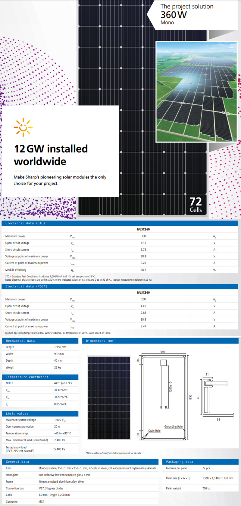
1. The following are the parameters of solar electric panels at the customer's site.
The following are the customer's on-site solar panel parameters:

2. Two-way DC energy metering
The customer requires a DC meter with two channels of direct current metering function, so two current shunts are needed to work with the meter.
Installation Pictures

